UML
UML Diagram Types and Examples
Sunday, June 2, 2013
UML Diagrams (Car Dealer)
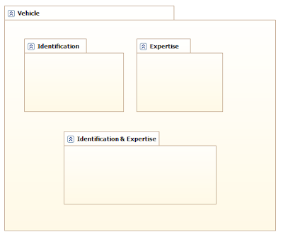
I wrote a program that name is Car Dealer. This software keeps records of car, customers, dealers and sales. I'll draw a few diagrams by rules of UML.
What is a UML Deployment Diagram?
Deployment diagrams depict the physical resources in a system including nodes, components, and connections.
Basic Deployment Diagram Symbols and Notations
Component
A node is a physical resource that executes code components.
Association
Association refers to a physical connection between nodes, such as Ethernet.
Components and Nodes
Place components inside the node that deploys them.
What is a UML Component Diagram?
A component diagram describes the organization of the physical components in a system.
Basic Component Diagram Symbols and Notations
Component
A component is a physical building block of the system. It is represented as a rectangle with tabs.
Interface
An interface describes a group of operations used or created by components.
Dependencies
Draw dependencies among components using dashed arrows.
What is a UML Activity Diagram?
An activity diagram illustrates the dynamic nature of a system by modeling the flow of control from activity to activity. An activity represents an operation on some class in the system that results in a change in the state of the system. Typically, activity diagrams are used to model workflow or business processes and internal operation. Because an activity diagram is a special kind of statechart diagram, it uses some of the same modeling conventions.
Basic Activity Diagram Symbols and Notations
Action states
Action states represent the noninterruptible actions of objects. You can draw an action state in SmartDraw using a rectangle with rounded corners.
Action Flow
Action flow arrows illustrate the relationships among action states.
Object Flow
Object flow refers to the creation and modification of objects by activities. An object flow arrow from an action to an object means that the action creates or influences the object. An object flow arrow from an object to an action indicates that the action state uses the object.
Initial State
A filled circle followed by an arrow represents the initial action state.
Final State
An arrow pointing to a filled circle nested inside another circle represents the final action state.
Branching
A diamond represents a decision with alternate paths. The outgoing alternates should be labeled with a condition or guard expression. You can also label one of the paths "else."
Synchronization
A synchronization bar helps illustrate parallel transitions. Synchronization is also called forking and joining.
Swimlanes
Swimlanes group related activities into one column.
What is a UML Statechart Diagram?
A statechart diagram shows the behavior of classes in response to external stimuli. This diagram models the dynamic flow of control from state to state within a system.
Basic Statechart Diagram Symbols and Notations
States
States represent situations during the life of an object. You can easily illustrate a state in SmartDraw by using a rectangle with rounded corners.
Transition
A solid arrow represents the path between different states of an object. Label the transition with the event that triggered it and the action that results from it.
Initial State
A filled circle followed by an arrow represents the object's initial state.
Final State
An arrow pointing to a filled circle nested inside another circle represents the object's final state.
Synchronization and Splitting of Control
A short heavy bar with two transitions entering it represents a synchronization of control. A short heavy bar with two transitions leaving it represents a splitting of control that creates multiple states.
What is a UML Collaboration Diagram?
A collaboration diagram describes interactions among objects in terms of sequenced messages. Collaboration diagrams represent a combination of information taken from class, sequence, and use case diagrams describing both the static structure and dynamic behavior of a system.
Basic Collaboration Diagram Symbols and Notations
Class roles
Class roles describe how objects behave. Use the UML object symbol to illustrate class roles, but don't list object attributes.
Association roles
Association roles describe how an association will behave given a particular situation. You can draw association roles using simple lines labeled with stereotypes.
Messages
Unlike sequence diagrams, collaboration diagrams do not have an explicit way to denote time and instead number messages in order of execution. Sequence numbering can become nested using the Dewey decimal system. For example, nested messages under the first message are labeled 1.1, 1.2, 1.3, and so on. The a condition for a message is usually placed in square brackets immediately following the sequence number. Use a * after the sequence number to indicate a loop.
What is a UML Sequence Diagram?
Sequence diagrams describe interactions among classes in terms of an exchange of messages over time.
Basic Sequence Diagram Symbols and Notations
Class roles
Class roles describe the way an object will behave in context. Use the UML object symbol to illustrate class roles, but don't list object attributes.
Activation
Activation boxes represent the time an object needs to complete a task.
Messages
Messages are arrows that represent communication between objects. Use half-arrowed lines to represent asynchronous messages. Asynchronous messages are sent from an object that will not wait for a response from the receiver before continuing its tasks.
Various message types for Sequence and Collaboration diagrams
Lifelines
Lifelines are vertical dashed lines that indicate the object's presence over time.
Destroying Objects
Objects can be terminated early using an arrow labeled "<< destroy >>" that points to an X.
Loops
A repetition or loop within a sequence diagram is depicted as a rectangle. Place the condition for exiting the loop at the bottom left corner in square brackets [ ].
Subscribe to:
Comments (Atom)

